We Got New Jobs

Ironically, it has been literally years since our last post here. There are several reasons for this, but the most pertinent one is that Caleb and I both have full-time jobs in the tech industry! Yay for us!

So, for the foreseeable future, there probably won’t be much going on in the Walke Designs wheelhouse. To keep abreast of our more personal matters, we both have various social media accounts, and Caleb is keeping a personal blog at Vantage Point, while I just started a programming blog at The Mullist.

I think I can speak for both of us when I say that we’re both glad to be doing what we love, but if you have an idea for an electronics automation project but don’t know where to start, we would still be glad to help you. I have a Raspberry Pi just itching to be put to good use.

New and Improved

Welcome to the re-designed Walke Designs home page. We’ve spruced up the look and made it easier for us to post new content here. No more waiting years for updates on your favorite small-town geeks.

Completed X-box Controller Color Modification

A long time ago when we first started Walke Designs one of the first ideas we had was to modify X-Box 360 controllers. We have really abandoned this idea for a while because it is such a simple thing to be done that anyone can do it. Even though its really simple not everyone wants to do it and upon seeing my controllers I have been contracted by a friend to modify two of his controllers. I decided to show what I have done here for everyone to see and keep notice of what Walke Designs is up to.


As you can see the modification is only an aesthetic one.


To commercially sell this product to anyone I would have to charge $20 for the basic button modification (Bumpers, Joysticks, bottom pane and triggers) that is assuming you supply the controller. If the controller is not supplied then I would need to raise the basic price to $70 to compensate for that. If you want anything beyond that (such as the yellow controller) we would need to discuss the modifications and come up with a custom price. If you are interested please drop us a line at info@walkedesigns.com.

Fall 2012 Update

We have been busy with many things here at Walke Designs and unfortunately have not been able to keep regular updates here on the website. Most of our exploits have been centralized around our school and work duties and thus Walke Designs has not officially done much.

We have not done much but have recently been contracted for three projects one of which we have already finished. I wanted to give an update on these to show what Walke Designs is doing.

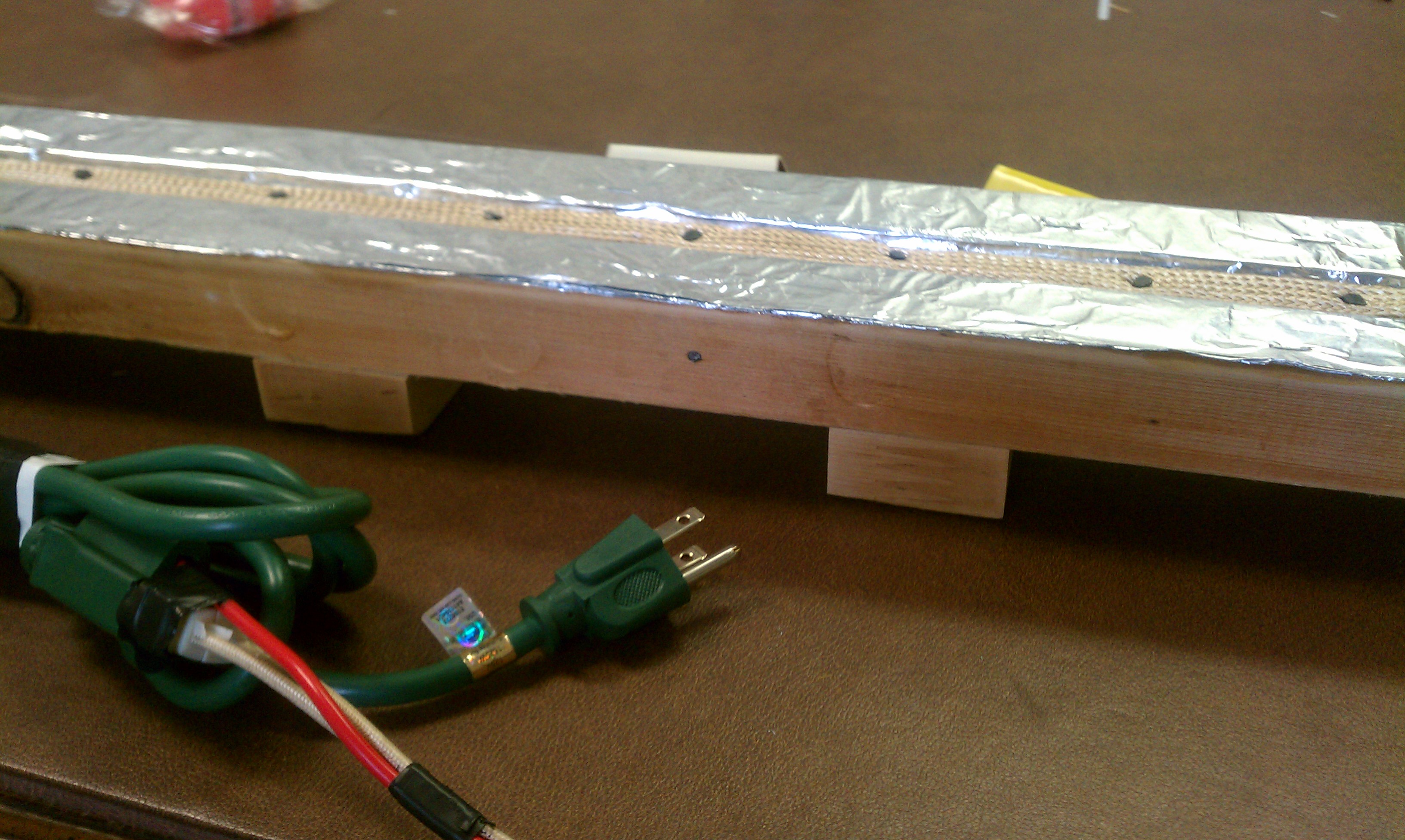
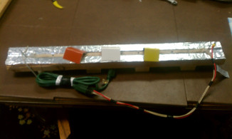
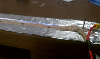
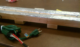
We were contracted to make a plastic bending device for a local sign maker. The plastic being bent is around 1/8 of an inch thick and 2 ply. We put together the plastic bender simply by insulating a heating element attached to a piece of wood. The heating element is also grounded to provide a little bit of safety. We estimate that if we were going to sell one we would need to sell it for about $200. That would cover all of our parts and labor costs. See below for some pictures of the final product. If you might be interested in purchasing one please contact us at info@walkedesigns.com.

We have been re-contracted to work on a Christmas lighting display for a church. This is the original project Walke Designs completed last Christmas. Basically the display will have a manger scene that will be light up separate parts at different times. We will have a really product here and need to be finished with this by thanks giving. If you might be interested in contracting Walke Designs please contact us at info@walkedesigns.com.

We also have been conscripted in the creation of an iPhone (and possibly Android later) application. The customer has designed and produced a board game and wishes to take it to the digital realm with an app. This is a different direction from our previous work being as this will be completely a software product. This project will be quite a large undertaking and will grow our business into a new realm. If you might be interested in contracting Walke Designs please contact us at info@walkedesigns.com.

Update 2

Well, it’s been too long since I posted an update on my progress with the project. I’ve spent a majority of the time getting everything
together for my IEEE Digital Design Contest submission. I got that submitted Sunday and now it’s time to get back full time to my RC car design.
Let me go over some of the decisions I have come up with in the meantime.

  1. First I have found an awesome chassis for my project. It’s 4-wheel drive, 1/8-inch aluminum and the motors are rated for about 7.2V running speed,
    giving the thing about a 7Km/h no-load speed. The tires on it are about 120mm in diameter giving it a good 60mm ground clearance.
  2. I’ve finished the design of my motor control circuit. Its super simple: I just copied the L298 IC design, just using
    MOSFETs with a high current tolerance for the motors, as the motors have a stall current of about 6.6A.

    Motor Control Circuit Schematic. Click to see full-size.

  3. I think for the time being for testing purposes I am going to use my “My Daq” made by National Instruments
    as my o-Scope and function generator for troubleshooting. It’s a good little device and I think it will work
    just fine for the applications that I need it for.
  4. Regarding the question of FPGA vs µC, µC is the answer. I decided to get a Microcontroller to run the PWM on my project. I found a really awesome
    company that makes test boards for them called Arduino. They are Italian in origin, but they are totally full of win.
    The programming system is open-source and based very closely on C. When you download the software for programming them it comes
    with a bunch of general programs on it that are commented excellently to help you learn how to use it. So far, an awesome buy.

My new question is that do need 2 µCs? I have worked on my x-box controllers a bit and I noticed that they have a µC
(or something) controlling the inner workings before data is sent to the main base station. Using 2 µCs might make this easier.
(one for the controller portion, and one for the motor control.)

That’s it for now I hope to get the motor control working on breadboard soon and I will have pictures and possibly videos for that when I do.
Here’s the current status of our master checklist:

  • [ ] Ascertain how to use antennas with this project
    1. What frequencies can I use?
    2. What ranges can be expected?
    3. Are there any IC’s that make this easier?
    4. Can information go both ways?
  • [X] How many L298 (H-bridge) IC’s do I need for 4 DC motors?

    2, but do I really need to run all 4 individually?

  • [X] Find a good chassis
    1. With some good DC motors
    2. Not too Big.
    3. Not too small.
    4. Around 9v Max running voltage
  • [ ] Find a good way to power all of this
    1. Perhaps adapt another battery pack from another RC car
    2. Something with enough power to run it for about 2 to 4 hours
    3. Preferably rechargeable.
  • [X] Find a way to be able to use an O-Scope and Function Generator for testing purposes
  • [X] FPGA or µC? That is the question
    1. Programming Language
    2. Price of Testing, SW, and Mounting
  • [ ] 1 or 2 µC?

Project Update

I thought I would give a quick update on my project so far.
I’ve been studying a lot for the last few days but when I get a few minutes I do some research on my side project.
So, I thought I’d update here on my “blog” if you want to call it that.

  1. If I wanted to run 4 motors separately I would need 2 L298 H-Bridge ICs.
    I’ve put some thought into this, though, and I’m not sure I really need 4-wheel drive.
    I mean having 4 motors in my project doesn’t mean that I will need to run all 4 separately.
    Each side of the robot will receive the same PWM signal, so there is no real need to run these motors separately.
    I’m thinking this would be better accomplished running each side in parallel.
    So, I see a possible issue with extreme power drain but that’s another bridge that I will need to cross. So, I will add that to the list.
  2. My search to find some good DC motors has also led me to search for wheels that will fit them and possibly a chassis that will house all of this.
    I originally wanted to make my own chassis and I had some hare-brained scheme imagining myself in the garage up late nights designing and building
    this chassis out of the old leftover cedar wood in the garage at home. I have come to the realization that a chassis made out of wood would really
    be impractical and generally not a good idea. So I’ve expanded my search to include looking for a good chassis, hopefully one that comes with motors and such.
  3. Troubles with the chassis have come to head since a lot of sites selling this type of equipment seem to leave out information I want to know.
    I can find an electric motor and they tell me the RPM and voltage but not the stall torque. I figure I need to know the stall torque to
    have an idea how much weight these motors can take, and how much speed they will give me. I’ll find a chassis that looks good but then they
    won’t have any dimensions. Before I drop some money, I want to make sure I’m not buying something the size of a match box.
  4. I did make some progress hunting for the answer to the ultimate question: “FPGA or µC?” I found an open source µC with a good
    amount of support that seems to be good enough to meet my needs. I found some sample programs for it, and it looks like the HDL is something
    really close to C++ which is good since that is a language I’m familiar with. It’s made by a company named Arduino,
    and it seems pretty cool. Now, on the equipment search, I found a handheld oscilloscope with a function-generating output on the internet
    for about $200. I’m thinking I might get it for my personal electronics needs. Reviews on it seem pretty positive. A friend of mine is getting
    one for Christmas, so I’m hoping to
    take a look at it and try it out a bit before I get one myself.

Let’s see where we are on the master checklist now:

  • [ ] Ascertain how to use antennas with this project
    1. What frequencies can I use?
    2. What ranges can be expected?
    3. Are there any IC’s that make this easier?
    4. Can information go both ways?
  • [X] How many L298 (H-bridge) IC’s do I need for 4 DC motors?

    2, but do I really need to run all 4 individually?

  • [ ] Find some good DC motors
    1. Not too Big.
    2. Around 9v Max running voltage
  • [ ] Find a good way to power all of this
    1. Perhaps adapt another battery pack from another RC car
    2. Something with enough power to run it for about 2 to 4 hours
    3. Preferably rechargeable.
  • [ ] Find a way to be able to use an O-Scope and Function Generator for testing purposes
  • [ ] FPGA or MC? That is the question
    1. Programming Language
    2. Price of Testing, SW, and Mounting

Remote Control Toy

I just got done with Project Lab 1 at Texas Tech and all in all it was a really good experience.
I won’t be in Project Lab 2 next semester because of a prerequisite conflict and I will most likely not be taking it this summer,
mostly because I want to go home and take classes there this summer. So, I decided to pick up a new hobby and design my own RC car from the ground up.
I’ve pretty much had to abandon all of my previous hobbies due to school and this is one I think I can justify as a good, worthwhile learning experience.
I also wanted to post regularly on Facebook and here so that anyone who wants to can follow my progress.
To get things started, I wanted to make a sort of checklist of things to do.

  • [ ] Ascertain how to use antennas with this project
    1. What frequencies can I use?
    2. What ranges can be expected?
    3. Are there any IC’s that make this easier?
    4. Can information go both ways?
  • How many L298 (H-bridge) IC’s do I need for 4 DC motors?
  • [ ] Find some good DC motors
    1. Not too Big.
    2. Around 9v Max running voltage
  • [ ] Find a good way to power all of this
    1. Perhaps adapt another battery pack from another RC car
    2. Something with enough power to run it for about 2 to 4 hours
    3. Preferably rechargeable.
  • [ ] Find a way to be able to use an O-Scope and Function Generator for testing purposes
  • [ ] FPGA or MC? That is the question
    1. Programming Language
    2. Price of Testing, SW, and Mounting

I plan to officially get started after the beginning of the year.